Experiment 5: Orifice Sizing (Large Sweep)
The final experiment in this tutorial will demonstrate a parameter variation of m_flow0 for the same orifice but for a much larger range. The purpose will be to demonstrate the upper limits of the orifice design. The previous experiment is duplicated and subsequently, the following modifications are made:
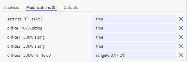
In this experiment, the design mass flow rate for the component orifice2_kW is simulated for a range of values from 0.8 kg/s up to 17 kg/s.
The experiment is titled "Experiment 5 - Orifice Sizing m_flow0 Sweep (Large Range)".
When simulated, name the result "PbS Orifice2 Sizing Large Sweep" and enable the system view "Orifice2 Diameter Sensitivity over Design Branch Factor"
The following plot is then visible:
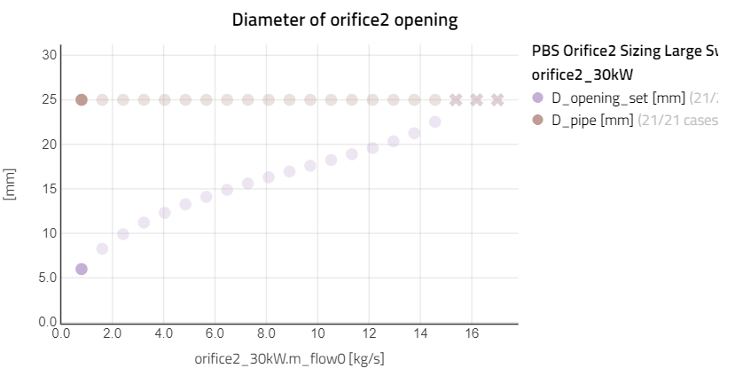
Figure 8: Results from experiment 5 -sensitivity analysis on orifice opening vs orifice design factor
The variable D_opening_set is the required orifice diameter needed to achieve the corresponding design flow rate m_flow0. It is apparent that for very large flow rates (higher than ca. 14.5 kg/s) no solution could be found for the orifice diameter sizing as the true required diameter would be larger than the surrounding pipe. Since the pipe diameter is set to 25 mm, any flow rates leading to an orifice diameter greater than this value cannot be solved. These runs are marked with an "X" point on the graph to indicate that the simulations have failed to converge.
This will also be indicated by a warning symbol in the simulation results as follows:

The point of demonstrating this parameter sweep over a very large range is to show Modelon Impact can be used to evaluate the upper (and lower) feasible limits for the sizing of components in a system.