Thermodynamic Cycle Initialization🔗
Background🔗
Modelon library product releases ship (various) plant models that are fully parameterized, simulation ready and configurable Thermodynamic Cycles. They are simulated as linked execution of thermodynamic processes that perform work, heat transfer, etc., using component models. The component models could be compressors, heat exchangers, pipes, valves, etc. Each component model is individually parameterized and simulated before being assembled into the larger cycle model.
Shown below in Figure 1 is a plant model which simulates one of the refrigeration and air-conditioning thermodynamic cycle.
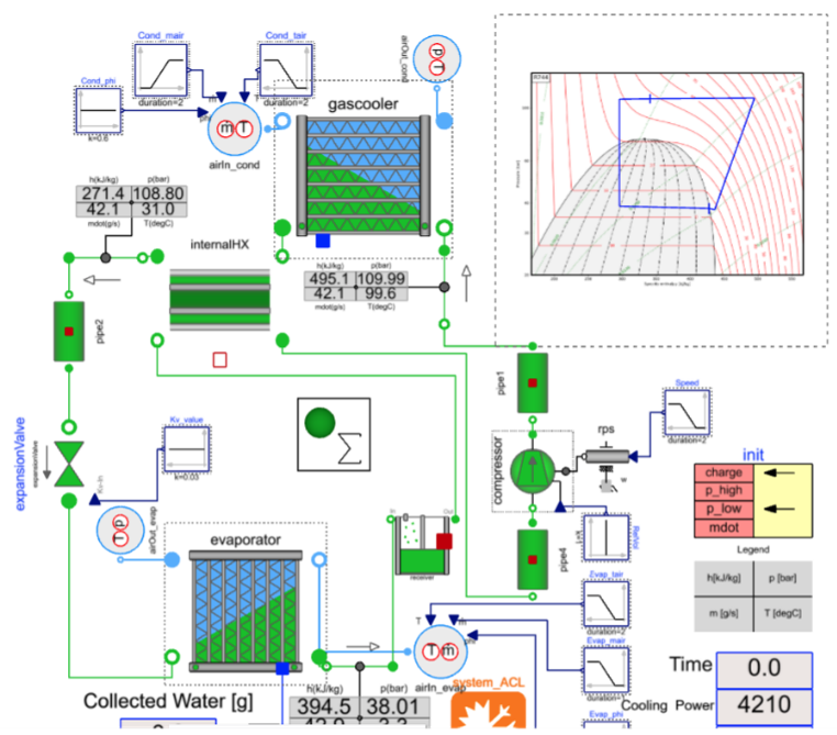
Figure 1. Closed cycle - CO2 as Refrigerant medium
Initialization failure example🔗
Initialization parameters are those that are provided as initial guesses or start values for the simulation to begin solving. Shown below in Figure 2 is an error message, that informs initialization has failed and the reason is pressure reaching to very small value.

Figure 2. Initialization error
This message can appear for the cycle model, or also for any individual component models (separate test bench). In this present case, it is pressure, otherwise exceeding the limit for temperature, enthalpy, density or entropy is also possible.
Always the initialization error messages are at time t = 0, which points out that one of the quantities specified as ‘Initial conditions’ is causing the simulation to venture into physically incoherent situations.
Some of the steps to resolve this error are as follows:
- Check if you have the correct medium selected for the cycle and also for all individual components.
- Search for any hints from error messages to find which component/model is causing this message.
- Re-evaluate the initial condition parameters for those components to check if they reflect the operating conditions.
- Evaluate if the user-prescribed initial conditions (Boundary conditions) operate within the physical bounds of the selected Medium.
- Initial condition parameters could also be present in a separate tab ‘Initialization’.
- Refer to the operating cycle initialization parameters at the init model and its correctness if applicable.
Init model🔗
As the plant model starts getting populated with more components, we reach towards full thermodynamic cycle system. The number of initial condition parameters for all the individual components also starts increasing. Besides, we also have the thermodynamic cycle operating values which we model on all the components. All the cycle-related initialization values are provided in the initialization model called ‘init’ as shown in Figure 3.
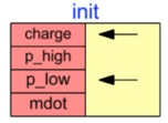
Figure 3. 'init' - Initialization error
For the full cycle simulations, often all the initialization conditions are influenced by the values provided in the init model. The values provided at init are internally reassigned as initialization parameters for component models.
Hence, error messages similar to what is shown in Figure 2 could appear, because of the initial conditions parameters that are provided in the init model.
Troubleshooting Initialization failures🔗
The below steps must be followed in a sequence.
- For such Thermodynamic cycle simulations, the error in Initialization values for the cycle’s components must be checked at the init model, rather than directly at the individual components.
- Check if the error message is on the refrigerant side or the secondary fluid/coolant side medium component (check the Heat Exchanger).
- Some of the init parameters are refrigerant mass flow rate, suction pressure, super heating temperature, specific charge initialization point etc.
- Make sure all components are already individually parameterized and simulated before assembling them into the larger cycle model.
- Check the operating conditions of your intended cycle and individual component’s qualified operating conditions.
-
Always refer to the p-h diagram and other relevant plots for your thermodynamic cycle.
For example with CO2, the increase in 10°C of temperature brings in about 10 kJ of increase in enthalpy at super-heated region. An increase of 10 bar in pressure can cause a change of about 10°C in two-phase regions. Hence the cycle initialization, init values must correspond to the cycle you are attempting to simulate through boundary conditions.
-
Giving the correct init model parameters or initial values will help the solver to start running effectively toward the given boundary conditions and cycle design.
- Once the solver crosses the initialization threshold after time t = 0 successfully, the boundary conditions, connections, and parameters fully influence the solutions of each and every component and the cycle at every time step.
- Refer to the visualizer as provided by Modelon in the cycle diagram to check where your simulation operates, especially after initialization is successful, and the solver starts running successfully.
The init parameters can vary slightly from cycle to cycle depending upon the refrigerant medium used, the plant model with component choices, and the intended cycle operating conditions.