Experiment 4: Orifice Sizing (Small Sweep)
Next, we will demonstrate how using another multi-run simulation, to perform a sensitivity analysis on the rightmost orifice component orifice2_30kW, namely, how the choice of design flow rate value m_flow0 (and subsequently, the orifice diameter) will have on the temperatures across all other components in the system.
- Navigate to the experiment: Experiment 4 - Orifice Sizing m_flow0 sweep (Small Range)
- Take note of the modifications applied in the experiment definition:
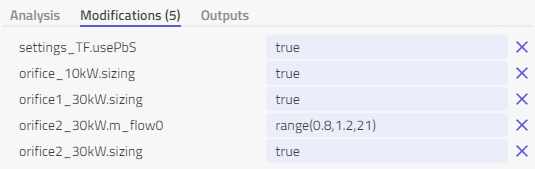
Again, since we are dealing with a steady-state problem, Modelon's Physics-based Solver (PbS) is enabled. The sizing parameter is set to true, such that the orifice diameter will be sized based on the design flow rate parameter m_flow0. The range( ) operator is applied to the design mass flow rate for component orifice2_30kW ranging between 0.8 kg/s and 1.2 kg/s over 21 individual runs of equidistant intervals. This is equivalent to taking a design factor range between 24 kWs/kg and 36 kWs/kg.
When simulated, the following plots can be enabled by selecting the system view Experiment 4 - Temperature Sensitivity to assess the influence of temperatures along selected points in the circuit:
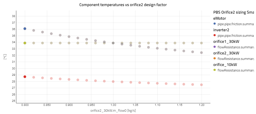
Figure 7: Results from experiment 4 -sensitivity analysis on component temperatures vs orifice design factor
The temperatures are plotted at the upstream fluid ports for the electric motor (eMotor) and inverter located in the same branch. As expected, there is no significant dependency on temperatures vs the set flow rate in other branches. Only components located in the same branch as orifice2_30kW (eMotor, inverter2) are influenced. The outlet temperature of eMotor illustrates the strongest dependency on the flow rate (steepest slope) with outlet temperatures varying from 32.5°C to 36°C over the range of flow rates tested. The outlet temperature of inverter2 displays a weaker dependency on the flow rate with outlet temperatures ranging from approx. 27.5°C to 28.8°C over the same range. This is due to the location of the inverter and electric motor relative to the coolant flow stream. As both components are in series, the temperature at the outlet of the component furthest upstream depends on the outlet temperature of the adjacent downstream component, thus will have a higher overall sensitivity to changes in flow rate. This is an important factor to consider when designing a TMS system with multiple components in series. It is common practice to place the most critical component (stricter temperature requirements) first in the series.