Problem Setup
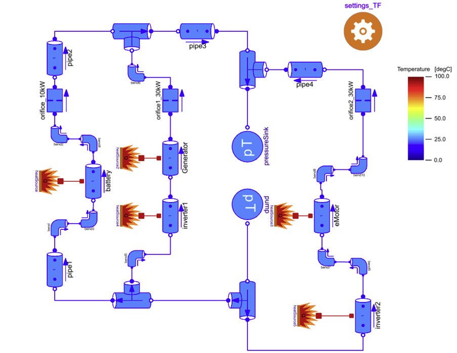
Figure 1: Orifice Sizing System Setup
The goal of the model is to solve a flow balancing problem, obtaining a suitable orifice sizing for a TMS consisting of three fluid branches connected in parallel which intend to cool down a number of components making up an electric propulsion system (EPS). Located on each branch is a flow-balancing orifice for which the opening diameter can be sized to control the mass flow rate.
The table below outlines the EPS components included in the model along with their corresponding heat loads and maximum permitted temperatures:
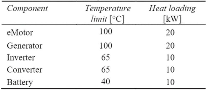
Table 1: Component heat loads and temperature limits
The following assumptions have been made for the purpose of simplifying the model:
- The pump is modeled with an ideal pressure boundary condition.
- The heat sink (e.g. ram air heat exchanger) is kept outside of the scope of this study, hence the system is an open circuit with ideal pressure and temperature boundary conditions acting as a source and sink.
- EPS components are modeled as ideal heat sources connected to pipes via a thermal port. Any thermal mass associated with the components is neglected here.
- Additional pipes and bends are added randomly to illustrate the capability of the tool.
In order to get a quick overview of the default conditions for the model, several predefined component views can be enabled when hovering over the eye symbol on the right-hand side of the model graphic:

By enabling the component views, case setup, and geometry, stickies will appear to see several input values such as the pressures and temperatures set at the source and sink boundaries, and pipe diameters as well as default values for the orifice diameter.
Physics-Based Solving
By enabling the component view PbS, a flag is displayed next to the component settings_TF called usePbS.
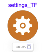
When the flag usePbS is enabled, it triggers instructions embedded in component models which guide the compiler and solver on iteration variables and residual selection for steady-state simulation. This language construct enables changing the iteration variables and residuals based on Boolean parameters, without the need for recompilation. The information is stored in an object-oriented fashion, such that modelers can assemble systems graphically, and the desired solving can be deduced from the model topology (model instances and connections). Modelon Impact's physics-based solver greatly enhances Modelica's solving capabilities for steady-state problems. As this flow balancing problem is assuming steady-state conditions, PbS will be enabled to solve the problem most efficiently.
Sizing Parameter
By selecting any of the orifice components in the system model, you will see the list of parameters used to characterize them under properties on the right-hand side panel:
Take note of the Boolean parameter sizing. Toggling the sizing parameter allows the user to parametrize the orifice in one of two ways:
1. sizing True: The orifice diameter will be computed based on a design mass flow rate m_flow0
2. sizing False: The orifice diameter is given directly as an input using the input D_opening and the mass flow rate is calculated accordingly.
Depending on the boundary conditions of the problem, the user may want to design the orifice in either of these two modes. The experiments below will outline cases for both.