Tank Sizing🔗
Introduction🔗
Hydrogen, to be used as fuel on an aircraft, first needs to be stored so it can be consumed during the flight. This is typically done either at high pressure around 6 or 7 hundred bar in its gaseous state or at a low temperature near -250°C in the liquid state.
Before we start🔗
You will need approximately 120 - 150 minutes to finish all the tutorial steps.
What are we building?
This tutorial focuses on liquefied hydrogen. The benefits of storing hydrogen in the liquid state are that for a given mass of hydrogen stored, despite having a fluid pressure near atmospheric pressure, the size of the liquid hydrogen tank can be roughly 800 times smaller than at ambient conditions. But how do we realistically implement this technology?
You will learn how to:
- Size the storage tanks under thermodynamic and mechanical constraints.
- Analyze the effect of filling rates on temperature and leakage.
- Pressurization and boil-off during storage with heat ingress.
- Maintaining temperature and reducing leakage while extracting fuel during flight.
Initial Setup🔗
- Log into Modelon Impact and create a new workspace named HydrogenStorage. This will generate a new workspace with only the Modelica Standard Library 4.0.0.
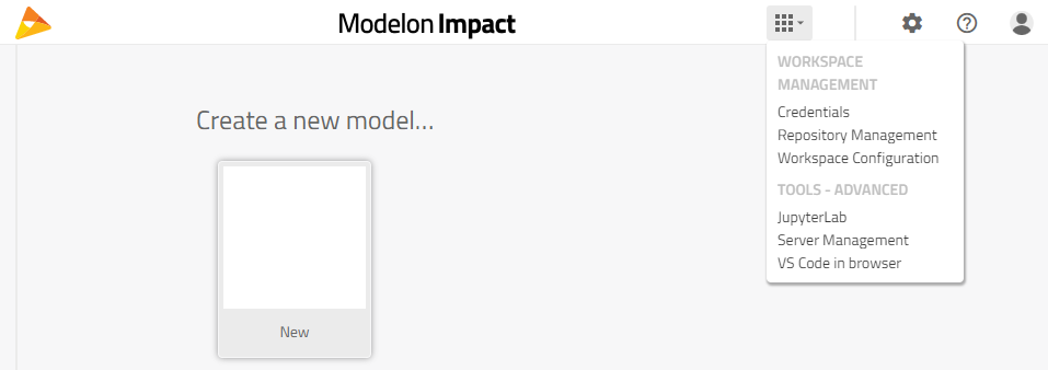
- We need to add Modelon 4.5 and Vapor Cycle Library 2.13. Open the Apps menu from the top toolbar and click on Workspace Configuration. A new tab will open.
- Click on Edit, then find and drag Modelon 4.5 and VaporCycle 2.13 from the Available Libraries list on the right into the area labeled “Drop libraries here to include them as dependencies”. Click Done and return to the previous tab. You will need to refresh the page for the new libraries to appear on the Libraries list if a prompt doesn’t already suggest so.
Sizing Experiment🔗
In this section, we will be using tank sizing models from the Vapor Cycle Library. They use cryogenic tank sizing methods suggested by Colozza [1] and by Huete and Pilidis [2]. Geometric parameters are determined by considering the key design factors of mechanical strength, structural design, heat transfer, insulation, dormancy and, boil-off. A revised dormancy estimation methodology by Sielemann et al [3] is used.
The tank sizing is coupled with aircraft sizing so that suitable design constraints are imposed. Therefore, the tank diameter must fit within the fuselage cross section and the overall mass of the tank including the hydrogen fuel is within limits imposed by the maximum take-off weight.
For this example, the storage tank for a two-aisle aircraft with the seating arrangement 2-3-2 (2 seats, an aisle, 3 seats, an aisle, then 2 seats) will be sized for a polyurethane foam insulated tank and a multi-layered insulation (MLI) vacuum insulated tank. This initial design constraint on diameter and weight would be done using the Aircraft Dynamics Library, but we’ll continue with those given by Sielemann et all [3].
The design parameters are shown in the below Table, and we’ll use this to find the appropriate length and wall layer thicknesses.
- The available hydrogen fuel in the Vacuum tank is less because the mass of the tank and the required accessories for a vacuum tank are more per volume than the foam-insulated tank.
- The foam insulation layer thickness is unknown but will be determined based on the 24-hour dormancy requirement.
- The MLI has a minimum practical thickness of 127 mm, so that will be a constraint and the dormancy will be determined.
- The Available hydrogen fuel determined from the aircraft sizing loop shows a higher capacity for the Foam than the Vacuum. This is due to the density of the vacuum’s MLI material, the minimum required thickness in addition to the higher mass of tank accessories per unit volume.
Size the Foam Insulated Tank (Foam232)🔗
- Create a new model: Workspace.SizingFoam232.
- Instantiate:
VaporCycle.Experiments.HydrogenStorage.TankSizing.Tanks.CryogenicFoam and rename it to foam232
-
Next, define the tank sizing problem (group = ‘Tank size parameterization’)
-
By coupling the tank sizing with the aircraft sizing we have constraints for the mass and outer radius. So, set sizeParameterization = “Prescribe mass and outer radius”
-
Set the mass of hydrogen fuel that would be available, massHydAvail_prscr = 13620 kg.
-
Set the outer radius, r_outer_par = 4.67 / (2) m.
-
Note
The CryogenicFoam tank model uses the following materials by default for each layer:
- layer1: aluminum pressure vessel.
- layer2: polyurethane foam insulation.
- layer3: aluminum protective shell.
-
Set the following parameters under the "Tank design – constraints and operating parameters" group:
-
Set the safety factor, sf = 2.2
-
Set the maximum operating pressure, p_max = 404 kPa (or 404e3 Pa)
-
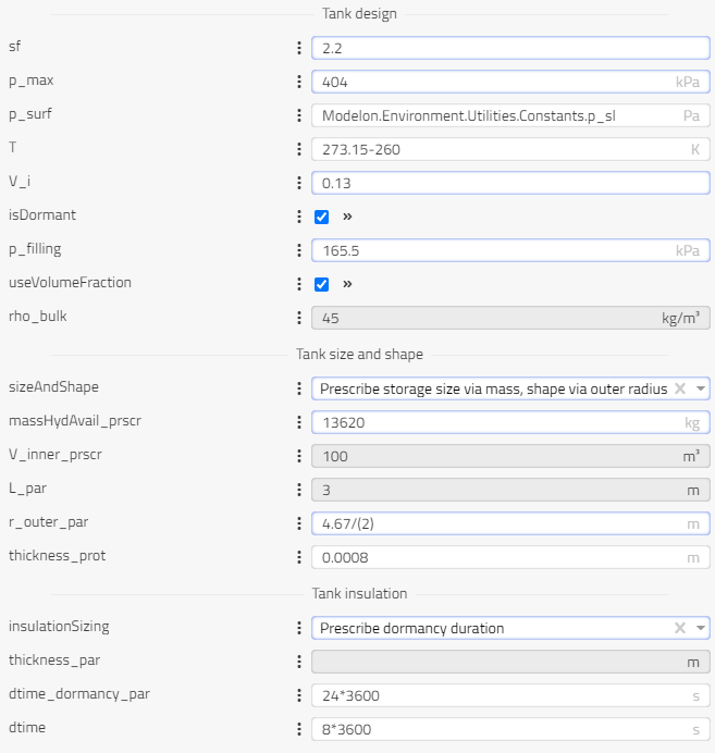
- Set the following parameter under the “Tank design – density” group:
- Set the percent volume reserved for vapor as a decimal, volumeFractionVapor= 0.13
- Set the following parameter under the “Tank design – dormancy” group:
- Set the internal tank pressure after filling, p_filling = 165.5 kPa (or 165.5e3 Pa)
- Then define how the insulation will be sized (group – ‘Tank insulation’)
-
The thickness of insulation is unknown so insulationSizing = “Prescribe dormancy duration”
-
Set the dormancy requirement as 24 hours, dtime_dormancy_par = 24*3600 s
-
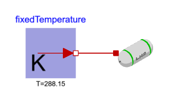
Instantiate Modelica.Thermal.HeatTransfer.Sources.FixedTemperature to represent the ambient temperature and connect it to foam232. Set the ambient temperature to T = 288.15 K.
-
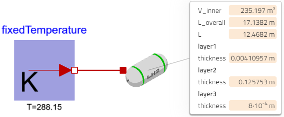
Simulate the model with Dynamic analysis and view results: We’ve defined the overall radius and mass then set design parameters for the mechanical strength and dormancy to solve for the storage tank’s length, volume and thicknesses of the wall layers. For the foam tank the outer protection layer is fixed to 0.8mm, but the inner vessel layer is computed based on the maximum pressure and mechanical strength while the insulation layer is computed from the required dormancy. In the result tab filter, search for the following variables:
-
V_inner = 235.197 m3 (Storage tank volume)
-
L_overall = 17.01579m (Overall tank length)
-
L = 12.3457 m (Length of the cylindrical section of the tank)
-
layer1.thickness = 0.0048 m (Innermost vessel layer thickness)
-
layer2.thickness = 0.117024 m (Middle insulation layer thickness)
-
layer3.thickness = 0.0008 m (Outermost protection layer thickness)
Size the Multi-Layered Insulated Vacuum Tank (MLI232)🔗
-
Create a new model: Workspace.SizingMLI232
-
Instantiate VaporCycle.Experiments.HydrogenStorage.TankSizing.Tanks.CryogenicVacuum and name it mli232.
-
Define the tank sizing problem (group – ‘Tank size parametrization')
-
By coupling the tank sizing with the aircraft sizing we have constraints for the mass and outer radius. So set sizingParametrization to = ”Prescribe mass and outer radius”
-
Set the mass of hydrogen fuel that would be available, massHydAvail_prscr = 10220 kg
- The MLI tank has more weight per volume than the foam so the mass of hydrogen it is capable of containing is less
-
Set the outer radius, r_outer_par = 4.67/2 m
-
Like the Foam232 tank, the MLI232 tank is constrained with the same fuselage cross-section.
Note
The CryogenicVacuum tank model uses the following materials by default for each layer:
- layer1: aluminum pressure vessel.
- layer2: vacuum insulation layer.
- layer3: aluminum outer layer to for buckling prevention.
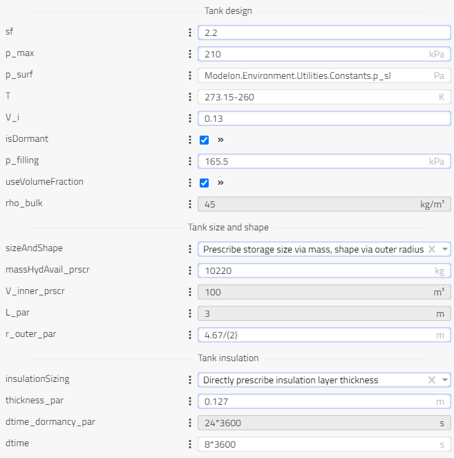
- Set the following parameters under the "Tank design – constraints and operating conditions" group:
-
Set the safety factor, sf = 2.2
-
Set the maximum operating pressure, p_max = 210 kPa (or 210e3 Pa)
- In group “Tank Design – density”:
- Set the percent volume reserved for vapor, volumeFractionVapor = 0.13
- In group “Tank Design – dormancy”:
- Set the internal tank pressure after filling, p_filling = 165.5 kPa (or 165e3 Pa)
- Then define how the insulation will be sized (group – ‘Tank insulation’)
-
For the Vacuum tank the MLI has a practical minimum insulation thickness so use insulationSizing = “Directly prescribe insulation layer thickness”
-
Set the prescribed thickness for the insulation layer, thickness_par = 0.127 m
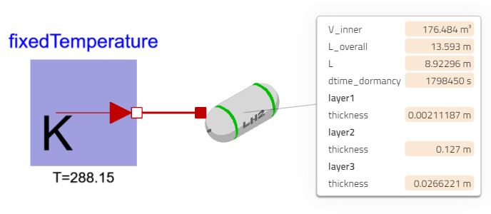
- Instantiate Modelica.Thermal.HeatTransfer.Sources.FixedTemperature and connect it to the mli323. Set the ambient temperature to T = 288.15 K.
- Simulate the model with Dynamic analysis and view results: Again, we’ve defined the overall radius and mass then set design parameters for the mechanical strength to solve for the storage tank’s length, volume and thicknesses of the wall layers. Since the insulation thickness was prescribed, look for the calculated dormancy. In the result tab filter, search for the following variables:
-
*V_inner = 176.484 m3
-
*L_overall = 13.6 m
-
*L = 8.93654 m
-
*layer1.thickness = 0.0033 m
-
*layer2.thickness = 0.127 m
-
*layer3.thickness = 0.0265 m
-
*dtime_dormancy = 1867520 s
As expected for the same aircraft design constraints, the foam tank can support a larger volume. The minimum required thickness for MLI vacuum insulated tanks and the extra mass from the bi-grid stiffened panel’s outer shell to avoid buckling used up the available mass limit. However, the MLI tank has a longer dormancy time, so it can store the low-pressure hydrogen longer without the need for venting or excess structural stress.
Impact on geometry🔗
The tank sizing models also support replacement for one or both end caps with a different geometry. Hemispherical end caps are the most implemented cap geometries, but sizing restraints might favor other geometries such as a flat plate or hemispheroidal cap. In the following example we will set the geometry of the end caps from the foam232 model to hemispheroidal and run a parameter sweep through a range of values for the ratio of the equatorial semi-axis s to r_inner (see model documentation for illustration):
-
Navigate back to the model Foam232 in the modelling mode.
-
Click on the instance foam232 and in the parameter group “Geometry Selection”, use the drop-down menu for the replaceable package StartSection and redeclare it as “Hemispheroidal”.
-
Do the same for the replaceable package EndSection and redeclare it to Hemispheroidal
-
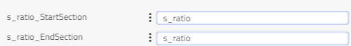
The parameters s_ratio_StartSection and s_ratio_EndSection should now be editable in the same group which represents the set values for the ratio s/r_inner for each end cap.
-
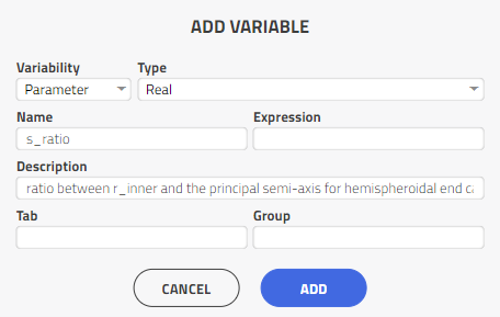
Next we will create new parameter at system level s_ratio which will be propagated to both end caps. On the right-hand side panel under Properties, select the plus symbol to create a new parameter.
-
Configure the parameter as type Real and provide a name and description like below:
We will then set the model parameters s_ratio_StartSection and s_ratioEndSection to the newly created top level parameter s_ratio to get as follows in the parameter dialog:
-
With this setup, we can now run a steady-state parameter sweep to adjust the curvature of each end cap simultaneously for each simulation run in the sweep by simulating a range of different values for s_ratio. Change to experiment mode and set the value of s_ratio to range(0.2,2,10). This sets the experiment to run a parameter sweep for values of s_ratio ranging between 0.3 and 2 over a series of 10 simulation runs.
-
Set the simulation mode to “steady-state” and ensure automatic_tearing=true, and interactive_fmu=false und compiler options.
-
Plot variables L_overall and eff on separate graphs to see the impact on varying length of the hemispheroidal cap shape on both the overall length of the tank and gravimetric efficiency.
-
Make a new plot with tank inner and outer radius r_inner and r_outer plotted on the same graph.
-
The following plots should then be visible (titles added afterwards for clarity):
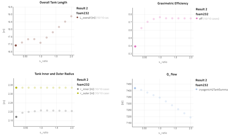
Figure 6: foam232 tank: relationships between gravimetric efficiency (eff), r_inner/r_outer and overall tank length(L_overall) for different hemispheroidal end cap lengths for a fixed outer tank diameter (4.67 m) and hydrogen storage mass (13,620 kg).
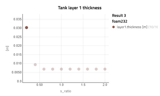
The plot of the tank gravimetric efficiency eff is the ratio of mass of hydrogen stored in the tank relative to the total mass of the tank + hydrogen. For shorter end cap curvatures, this leads to a higher thickness requirement for the inner tank layer (pressure vessel) thus a higher overall tank mass for the same storage mass of Hydrogen. This thickness requirement is more clearly seen when plotting the variable layer1.thickness as shown in the plot below. One can observe this rapid improvement of tank efficiency as the ratio s_ratio increases with a general flatting for values higher than approx. 1.
For the overall length of the tank L_overall however, there exists a more complex relationship between it and the length of the equatorial axis s For shorter curvature lengths (s_ratio=0.2) of the end caps, the overall tank length can be reduced in comparison to the hemispherical end cap case with s_ratio=1 while still retaining the same mass of hydrogen and outer tank diameter. As to be expected, larger end cap curvatures (oblate hemispheroidal) lead to a higher overall tank length, despite some reduction in heat ingression. This sweep illustrates a tradeoff between gravimetric efficiency, heat flow and overall tank length for varying the equatorial semi-axis lengths of the tank end caps. Oblate hemispheroids (where s > r_inner) lead to lower heat losses at the expense of a longer overall tank length for the given sizing parametrization option. Since the hemispherical end cap delivers the greatest value gravimentic efficiency while still resulting a in a relatively low overall tank length, it will be assumed that both tanks will keep to this hemispherical geometry for the subsequent experiments.
Note
By changing sizingParametrization to a different parametrization option and running a similar parameter, different trends can be observed, which may favor other geometries.