Get Started🔗
To use the examples and tutorial for Hydrogen Powered Aircraft application:
Click the button below to import the workspace in Modelon Impact
Gaseous Hydrogen Refueling🔗
This example represents a hydrogen tank that gets filled by a refueling station, where gaseous hydrogen is prechilled and compressed into a buffer volume where it is dispensed into the fuel tank or recirculated back to the fuel supply. The component models used are from the Modelon Base Library and the Vapor Cycle Library.
Predefined experiments are set up to demonstrate this system for different operating conditions, such as:
- Compressed hydrogen at medium to high pressure (350-700 bar)
- Cryo-compressed hydrogen at medium pressure (350 bar)
Read more
System description
The hydrogen storage
The hydrogen storage model, tank, is Modelon.ThermoFluid.Volumes.TanksWithDetailedWall.HorizontalCylinderSpheroidalEnds. It is two-phase fluid volume for a horizontal cylindrical tank with spheroidal end caps. The length of the cylinderical section is L = 2 m and the radius is r_internal = 0.5 m. The wall is t_wall = 0.15 m thick and uses property data for medium density polystyrene foam.
The phases in the tank are not necessarily in equilibrium and different heat transfer correlations are used between the wall and the different phases. The wall of the tank is descretized along the height of the tank and the heat transfer between the wall and the two phases depends on the liquid level.
Connected to the heat ports of the tank are thermal conductance blocks and a temperature heat source. The three heat ports represent the two end caps and the cylinderical section, each are vectorized to match the descretization of the tank wall. In this example, the conductance is zero to consider a pefectly insulated tank.
Above the tank, connected to the vaporPort is checkValveMBL, which opens to expell gas to the pressure sink, atmosphere, to avoid the tank reaching its maximum pressure.
The refueling station
The rest of the system model that is conencted to the tank, represents a refueling station. The pressure boundary, source, is the supply of pre-chilled hydrogen fuel at, p_source = 350 bar and a temperature that corresponds to the intended storage requirement. The compressor pressurizes the hydrogen in a buffer volume to prepare it for dispensing maintained at p_supply = 825 bar. From the buffer volume, excess fuel is split through checkValve for recirculation into the supply and cooling loop represented by the pressure sink, recirc. In the other leg of the split, the valve, varFlowCoeffValve is managed by a controller to open until a flow rate is met and closes after a total mass of fuel has passed through.
On the controller, dispenserControl:
M_fill: The total mass of fuel to dispensemflow_fill: The target mass flow rate to refuel witht_start: Time in experiment to start refueling
Experiments
Switch to the Experiment mode (or press [2] on the keyboard), on the right-side panel there is an Experiments section with predefined experiments ready to simulate. All experiments run a 1000 second simulation with the same system parameterization. The differences are within the boundary and operating conditions. Below are descriptions of each of the experiments:
CryoGas
This is the default experiment.
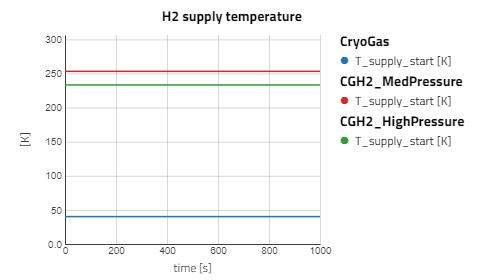
- Supply temperature:
T_supply_start= 40.15 K - Tank pressure:
p_tank= 350 bar - Hydrogen mass refuel target:
dispenserControl.M_fill= 75 kg
CompressedMedPressure
This is the experiment is for compressed gaseous hydrogen (CGH2) at medium pressure, which is chilled but not to cryogenic temperatures and at the same pressure as CryoGas.
- Supply temperature:
T_supply_start= 253.15 K - Tank pressure:
p_tank= 350 bar - Hydrogen mass refuel target:
dispenserControl.M_fill= 75 kg
CompressedHighPressure
This is the experiment is for compressed gaseous hydrogen (CGH2) at high pressure, which is chilled more than CGH2 at medium pressure.
- Supply temperature:
T_supply_start= 233.15 K - Tank pressure:
p_tank= 700 bar - Hydrogen mass refuel target:
dispenserControl.M_fill= 75 kg
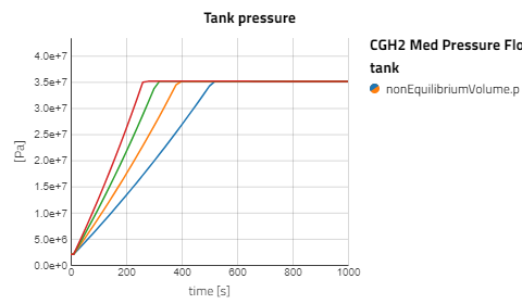
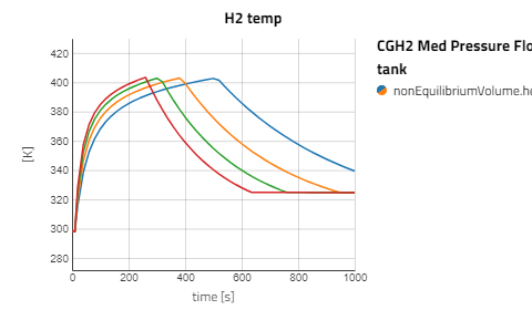
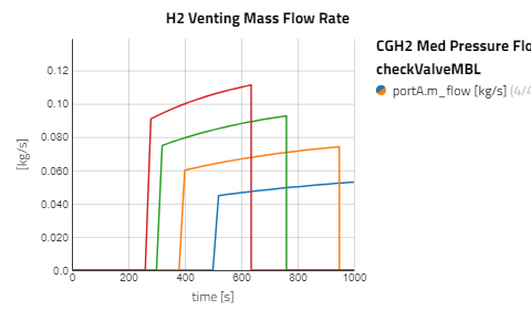
CGH2 Med Pressure Flow Sweep
This is the experiment is to observe the affect flow rate has for the compressed gaseous hydrogen at medium pressure
- Supply temperature:
T_supply_start= 253.15 K - Tank pressure:
p_tank= 350 bar - Hydrogen mass refuel target:
dispenserControl.M_fill= 75 kg - Refueling flow rate:
dispenserControl.mflow_fill= choices(0.06,0.08,0.10,0.12) kg/s
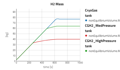
Results
After simulating the experiments, hover over the eye-con to see the predefined Views and use result under System views to plot key variables from the system simulation.
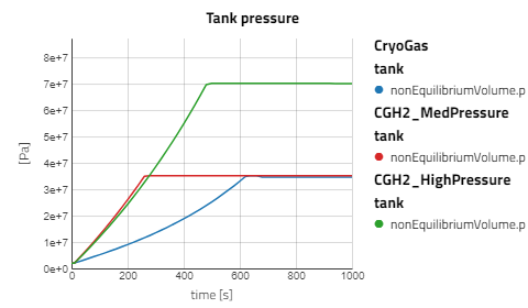
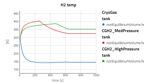
Use the views to compare the results between the experiments for compressed gaseous hydrogen at medium and high pressure versus cryo-compressed hydrogen gas. Using the same refueling profile, we can see that more hydrogen mass can fit within the tank for CryoGas before the check valve opens to relieve the tank pressure. It's also noticeable how important pre-chilling is for the high pressure compressed gas to avoid high temperatures during fill up.
The CGH2 Med Pressure Flow Sweep experiment has 4 cases so enabling the view for just that result alone will be easier to analyze. It can be seen that with lower flow rates, the tank pressure and temperature don't rise as fast and the rate at which the hydrogen needs to vent is slower.
Hydrogen Fuel Cell PowerTrain🔗
This example is a hydrogen fuel cell powertrain consisting of hydrogen storage, a PEMFC stack, a humidifier, coolant and air flow. The component models used are from the Modelon Base Library, the Vapor Cycle Library, and the Fuel Cell Library.
Predefined experiments are set up to demonstrate the fuel cell operation while ambient air conditions change based on a flight mission profile prescribed to the airData block.
Read more
System description
This aircraft powertrain system uses ambient air for its cathode air source, so airData, atmosphere, and worldRepresentation blocks are used to describe the position and movement in space while also providing the corresponding properties of the atmosphere.
In this 1000 s experiment, the altitude begins at 0 m and after 200 s will ramp up to 1500 m over 500 s. Meanwhile, the speed will remain constant at 0.2 Mach.
Fuel cell
The system uses a proton exchange membrane fuel cell (PEMFC) stack. Hydrogen fuel is used on the anode side while ambient air that has been humified is fed to the cathode side. Cooling water flow is controlled by a PID that monitors the stack temperature.
Hydrogen storage
The hydrogen storage model, tank, is Modelon.ThermoFluid.Volumes.TanksWithDetailedWall.HorizontalCylinderSpheroidalEnds. It is two-phase fluid volume for a horizontal cylindrical tank with spheroidal end caps. The length of the cylinderical section is L = 2 m and the radius is r_internal = 0.5 m. The wall is t_wall = 0.15 m thick and uses property data for medium density polystyrene foam.
The phases in the tank are not necessarily in equilibrium and different heat transfer correlations are used between the wall and the different phases. The wall of the tank is descretized along the height of the tank and the heat transfer between the wall and the two phases depends on the liquid level.
Connected to the heat ports of the tank are thermal conductance blocks and a temperature heat source. The three heat ports represent the two end caps and the cylinderical section, each are vectorized to match the descretization of the tank wall. In this example, the conductance is zero to consider a pefectly insulated tank.
Above the tank, connected to the vaporPort is checkValveVent, which opens to expell gas to the pressure sink, ambient, to avoid the tank reaching its maximum pressure.
Anode flow system
The anode flow system is the supply and recirculation of hydrogen fuel for the fuel cell. From the tank the hydrogen gas passes through valveAnodeFeed, with its opening controlled to a target outlet pressure. A fluidConverter is used to convert from the HydrogenMBWR medium package used by the tank to the appropriate medium package compatible with the fuel cell model (Note: The anode output uses a condensing version of the medium package, so another fluidConverter is required for the recirculation with the feed).
After the fluid conversion, a simple volume is used as a preheater before it enters an ejector which combines with the recirculated fuel before entering the fuel cell's anode channel. From the anode outlet, remaining fuel is recirculated to the ejector's suction port. The checkValvePurge will send the excess anode outflow to a sink.
Ambient air and cathode flow system
Ambient air flow starts at sourceCathode, where the pressure and temperature are inputs from the atmosphere model. The air gets compressed through the compressor stage of a turbocharger. A controller is used to for the compressor speed based on the hydrogen consumption on the anode side and the stoichiometry. The airflow then passes through the humidifier, where moisture is added from the condensation of the cathode outflow. The humidifier also preheats the airflow using the spent coolant from the fuel cell's cooling system.
The cathode outflow passes through the condenser_pump, which has a controlled pump to feed condensed water to the humidifier based on the cathode feed's relative humidity. There is a bypass to avoid the condenser volume from overflowing and the rest of the airflow is sent through the turbine stage of the turbocharger before exiting to an ambient pressure sink.
Experiments
Switch to the Experiment mode (or press [2] on the keyboard), on the right-side panel there is an Experiments section with predefined experiments ready to simulate.
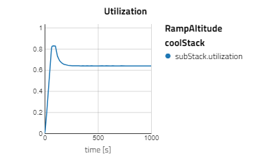
RampAltitude
This is the default experiment where the system moves at a constant velocity and increases altitude over a portion of the simulation time.
- Altitude: Begins at 0 m then ramps up to 1500 m from 200 s to 700 s
- Target relative humidity of cathode feed:
RH_stack_setpoint= 0.9 - Fuel feed temperature:
Tin_fuel= 298.15 K - Fuel feed pressure: 1.55e5 Pa
SweepAnodeTemp
This experiment keeps the system at a constant altitude and varies the temperature at which the hydrogen fuel gets preheated to and observes the effect it has on the fuel cell performance.
- Altitude: 0 m
- Target relative humidity of cathode feed:
RH_stack_setpoint= 0.9 - Fuel feed temperature:
Tin_fuel= choices(225.15,278.15,298.15) K - Fuel feed pressure: 1.55e5 Pa
ConstantAltSweepRH
This experiment keeps the system at a constant altitude and varies the controlled relative humidity of the cathode feed.
- Altitude: 0 m
- Target relative humidity of cathode feed:
RH_stack_setpoint= choices(0.8,0.85,0.9) - Fuel feed temperature:
Tin_fuel= 298.15 K - Fuel feed pressure: 1.55e5 Pa
Results
After simulating the experiments, hover over the eye-con to see the predefined Views and use Summary under System views to plot key variables from the system simulation.
Use the views to compare the results between the experiments for compressed gaseous hydrogen at medium and high pressure versus cryo-compressed hydrogen gas. Using the same refueling profile, we can see that more hydrogen mass can fit within the tank for CryoGas before the check valve opens to relieve the tank pressure. It's also noticeable how important pre-chilling is for the high pressure compressed gas to avoid high temperatures during fill up.
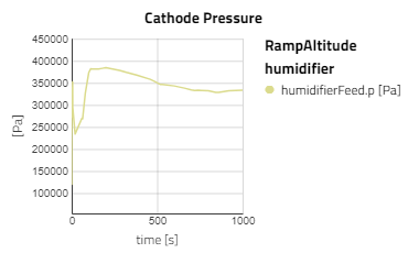
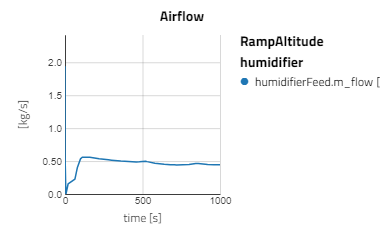
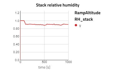
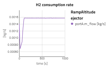
Below are some plots from RampAltitude, it can be seen that the rise in altitude decreases the ambient air pressure and temperature, then in turn, the cathode feed pressure and temperature also decreases. However, there is not a noticeable effect on the fuel cell's performance, utilization of the hydrogen fuel is steady over the altitude climb. This is because controls are in place to maintain the fuel cell conditions, like the anode feed temperature and pressure, the cathode relative humidity and the stack temperature.
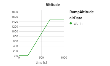
Note: alt_in is a real input connector for airData the expected unit is meters.
Liquid Hydrogen tank sizing app🔗
Demonstrates a liquid hydrogen storage tank model for sizing applications.
Read more
This example simulates a sealed cryogenic hydrogen storage tank with heat ingress. The tank is a vertical cylinder with 2 m internal diameter, and 2.5 m internal length. The initial tank pressure is 3 bar and the vapor and liquid phase are initially both at saturation temperature of approx. 24.6 K. The initial liquid level is at 1.2 m, just below 50% full. At the start of the simulation, liquid heating of 1 kW is initiated. The heat ingress cause the temperatures, as well as the pressure to rise. After little less than 1 hour, the pressure reaches 3.5 bar. At this point a safety valve opens, allowing vapor to exit the tank to avoid too high pressure. With the valve open, pressure settles at 3.5 bar, and the boil-off rate settles at 2.3 g/s.
Self pressurization Hasan🔗
Hasan, et. al. measured the pressure and temperature at different heights inside a sealed spherical hydrogen tank [1]. This example replicates their experiment from the 3.5 W/m2 case.
Read more
Hasan, et. al. measured the pressure and temperature at different heights inside a sealed spherical hydrogen tank [1]. This example replicates their experiment from the 3.5 W/m2 case. The tank is spherical with a volume of 4.89 m3, and the initial filling 83 - 84 % liquid hydrogen. Two different initial conditions are tested: Roughly isothermal conditions (small temperature differences inside the tank) and steady boil-off rate (a temperature profile has stabilized inside the tank so the boil-off rate is constant). The initial pressure is 1.03 bar.
In this example model, all thermal resistance was concentrated to a single heat transfer coefficient, and that was calibrated to match the observed pressure rise rate after is has stabilized.
The liquid was assumed to be initially saturated and the vapor temperature was set to have temperatures initially according to measured values.
The liquid - vapor heat transfer coefficient was calibrated to match the vapor temperature to the measured one after it had stabilized. No additional calibration was made to match the initial temperature response of the vapor in the isothermal case, however it matches well.
The pressure rise rate is initially too small and after long time the difference in pressure for the two initial scenarios is also too small. This is understood to be caused by the assumption of uniform liquid temperature, where in reality there will be a subcooled liquid bulk and a saturated boundary layer. The thickness of this layer would be different following the two different initial conditions, influencing the pressure. However that effect is not captured here.
Digitized pressure and temperature measurements are read into the simulation result to simplify comparison.
Reference
1. Self-pressurization of a flightweight liquid hydrogen storage tank subjected to low heat flux, M.M. Hasan, C.S. Lin, N.T. Van Dresar, NASA Technical Memorandum 103804, 1991.
Liquid withdrawal Huete 5h🔗
In their paper, Huete & Pilidis [1] performed parametric study on conceptual hydrogen tanks for civil aviation propulsion. One of the studied parameters is the tank diameter of a cylindrical hydrogen tank. At constant volume, different diameter - length aspect ratios give different heat transfer area per volume, and thererby influencing the pressure rise rate during storage and liquid withdrawal.
Read more
In their paper, the pressure time derivative versus tank diameter for constant liquid extraction rate and total tank volume. The trend is high dp/dt of ca. 150 kPa/h for 1.5 m diameter, then initially rapid decrease of dp/dt with increased tank diameter, but decrease rate reducing the greater the tank diameter.
This example model takes the available parameter from the paper, and defines top level parameters for diameter, total volume and liquid withdrawal rate. The required tank length is computed and specified to the tank. This way the diameter can easily be varied with constant volume.
The result, shown below, indicate the same trend. The plotted result is pressure rise rate [kPa/h] for 5 h simulations at diameters from 1.5 to 6 m. The smallest diameter give the greatest pressure rise rate, and increasing the diameter has largest effect at smallest diameter. This is consistent with the findings in [1].
Reference
1. Parametric study on tank integration for hydrogen civil aviation propulsion, Jon Huete, Pericles Pilidis, Int. Journal of Hydrogen Energy 46, 2021.
Hydrogen Evaporation🔗
Example heat exchanger model where liquid cryogenic hydrogen is evaporated by feeding it through a heat exchanger with ambient air as secondary fluid.
This example simulates a sealed cryogenic hydrogen storage tank with heat ingress.